Thursday, April 13, 2017

AZURE CONNECTIVITY MIGRATION FROM IPSEC VPN TO EXPRESS ROUTE

Recently I got the opportunity for migrating one of the Azure customer from his existing IPSEC VPN to Express Route. After doing some research and going through multiple scattered documentation, I was able to do the migration successfully. The whole process will normally take around 90 to 120 minutes. I decided to make this post to consolidate the entire process together for future migration.

Assuming that the Express Route is already provisioned by your provider, the procedure goes as follows:

1. During the initial IPSEC VPN configuration, gateway subnet was created. For IPSEC VPN, the length of the subnet is /29 but for Express Route the length has to be /28. Unfortunately you can’t change this subnet if the IPSEC VPN is still in use.


2. In order to change the gateway subnet, you need to first delete the IPSEC VPN under VIRTUAL NETWORK GATEWAY --> CONNECTIONS


3. Delete the VIRTUAL NETWORK GATEWAY. This step can sometimes take upto 30 to 40 minutes.


4. Delete the gateway subnet under VIRTUAL NETWORK --> SUBNETS --> GATEWAYSUBNETS and create it with /28 as the mask.
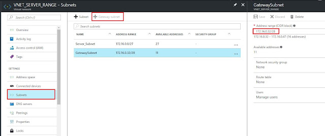


5. Create the VIRTUAL GATEWAY again but this time select the gateway type as EXPRESS ROUTE. Select the appropriate VIRTUAL NETWORK and RESOURCE GROUP. Note that you have to select PUBLIC IP ADDRESS as well but it won't be used for Express Route configuration. This step will again take upto 30 to 40 minutes.


6. Last step will be to link your EXPRESS ROUTE connection with the VIRTUAL NETWORK. For that, you need to go to EXPRESS ROUTE --> CONNECTIONS --> ADD. Select the appropriate VIRTUAL NETWORK GATEWAY (created above) and EXPRESS ROUTE CIRCUIT.


7. Once the EXPRESS ROUTE is linked to VNET successfully, your provider should start receiving the VNET subnet on the BGP session.


Wednesday, April 12, 2017

TOOLS/WEBSITES FOR CREATING NETWORK DIAGRAMS

Since the beginning of my career I have been only using Microsoft Visio for creating network diagrams. Being a Microsoft product, its easy to use and gets your job done most of the time. The only problem apart from the hefty price tag is the concept of stencils. You need to find the right stencil for the products you need to show in your diagram else you end up either using some generic shapes or using images in place on actual ones.

After doing some research and reading some forums, I have created list of other software/websites that allows you to do the same job in a different way. Some of them are free while others require license.


Tuesday, April 11, 2017

HOW TO DO NETWORK AUDIT!

Many times engineers need to do network audit for their customers or their potential customers with whom they are planning to sign contract with in future. There is no standard rule or technique on how the network audit should be done but people have worked out few steps which will help you during the whole process.


CREDIT: /u/VA_Network_Nerd


  •     Go one switch at a time, starting from the Internet router and map out the Layer-1 physical topology first.

  •     Ignore VLANs and Subnets at first. Just nail down what is plugged in where. A spreadsheet of interface descriptions and a pencil & paper doodle would be the go-to tools.

  •     For the Layer-3 logical topology, document where all the subnets and HSRP members are, as well as STP priorities.

  •     Go switch by switch identifying what ports are in what VLAN. The initial 80% of the drawing is pretty easy. The final 20% can be pretty painful.

  •     Try to understand the topology by looking at MAC Address counts per port. An end-user port shouldn't have more than 3 to 5 MAC addresses on it. If you have more than that on a port, there is probably another switch on the far end - go find it.

  •     Once all of that is done, re-visit each closet and make sure each device had a clear name tag front & rear -- YES label them on the back too. Help you avoid yanking the wrong power cable some day. Then update the switch port interface descriptions in accordance with some kind of a naming convention standard.

  •     Correct the STP priorities to reduce the chance of any surprises later on. In my opinion, the correct STP topology goes like this:    
  1.     RPVST up to 500 or so VLANs. Any more than that, MST is the better tool.
  2.     The root-bridge is priority 8192. The alternate root is 12288.
  3.     Every single switch DIRECTLY attached to either of those is 16384.
  4.     Every single switch DIRECTLY attached to those is 20480.
  5.     Keep adding 4096 to each layer of the topology beyond that.

  •      Apply DHCP Snooping and Port-Security at the user edge.

  •      Correct SNMP, Syslog and NTP to comply with standards.

  •      Convert your doodles and notes to pretty diagrams in Visio and Spreadsheets and call it a day.

WHAT IS SD-WAN?


 What is SD-WAN?

Software-Defined WAN is an application-aware service that intelligently routes traffic in real time, based on established business policies, along with network quality and availability.

It’s based on Software-Defined Networking (SDN) that separates the overlay network from the physical WAN, and network function virtualization (NFV) that enables the virtualization of network services using commodity hardware. SD-WAN determines the most effective way to dynamically route traffic to multiple disparate locations, uses open hardware software standards to run NFV features, enables the use of all available circuits, and centralizes the management of all connection points into a single view.

MPLS vs SD-WAN

Many businesses that require the security and performance of a private WAN have built hybrid WAN architectures that combine traditional MPLS-based networks with readily available options like dedicated Internet. While this solves for any-to-any connectivity, it can compromise performance and security and increase costs and complexity due to capital outlay, internal resources and vendor management.
As demand for cloud applications and services continues to grow, enterprises are re-examining their WAN strategies and architectures to optimize business efficiencies, protect critical data and enhance the user experience across public, private and cloud paths. SD-WAN decouples network intelligence and configuration from physical connections and hardware (via an abstracted layer) to create a scalable, centrally managed virtual voice and data WAN that connects distributed branches and remote locations regardless of connection type, access point or carrier.

Introducing SD-WAN

64% of U.S. based companies are in stages of planning to implement or expanding implementation from a traditional WAN to an SD-WAN solution in the next 12 months*. And for good reason. SD-WAN delivers everything your network needs to be agile, efficient and ready for the cloud era.

SD-WAN topology diagram indicating the relationship between a headquarters and branch site, incorporating MPLS, IP-sec, VoIP, 4G LTE, firewall, SaaS, and the public internet.]

Simplify network management

Converge voice, data and video applications on the same IP backbone and use existing hardware and available access types to connect locations. Now you can reduce capital investment, lower provisioning time and simplify technology migration. There are no manual switches to engage or monitor, plus a centralized portal that offers deep visibility. Automatic updates and upgrades ensure no downtime or business interruptions.

Keep critical data safe

Your employees want ubiquitous access from anywhere, and it’s your job to keep data safe and secure. Now you don’t have to choose. A secure abstracted overlay creates a virtual private network on top of existing connection points. All network traffic is encrypted over public or private paths, for security in a borderless environment.

Increase efficiency and resiliency

Determine the most effective way to dynamically route traffic to multiple locations. Business policies automatically prioritize and de-prioritize traffic, making better use of bandwidth to enhance application performance and overall user experience. What’s more, dual active links provide redundant and/or diverse connections at each site, increasing network resiliency.

Scale easily

With rapid site deployment and standardized low-touch provisioning, you’ll hit the ground running while transferring any capital outlay risk, network configuration and maintenance to your SP. When you’re ready to grow, the solution scales seamlessly to accommodate new sites with easily activated circuits to meet your ongoing business needs.

Next-generation features

  • Hybrid WAN: Integrates private and public links into one hybrid architecture
  • Flexible connectivity: Ubiquitous access connects disparate locations
  • Private network: Secure abstracted overlay creates a VPN across connection points
  • Software-based: Converges voice, data and video apps with low-touch provisioning
  • Dynamic path selection: Business policies automatically prioritize and de-prioritize traffic
  • Dual active links: Redundant and/or diverse connections at each site
  • Centralized management: ‘Single pane of glass’ customer portal
  • Managed service: SP manages, maintains and monitors the solution for all networks

Benefits

  • Support increasing use of cloud-based applications
  • Protect data across all locations
  • Lower CAPEX and transfer outlay risk
  • Optimize performance across network applications
  • Boost network resiliency
  • Simplify network management
  • Gain greater visibility over network traffic
  • Reduce OPEX and IT management time
  • Increase business agility and scalability

CREDIT: https://www.windstreambusiness.com/solutions/network-data-services/sd-wan

Monday, August 6, 2012

HOW TO DESIGN/BUILD A NETWORK

Ever wonder what is the best way of designing/building a network? Considering different layers, sizing, configuration, redundancy,management etc to build a solid scalable enterprise network. The following link from Cisco describe the best practice design while building a network along with sample configuration.

Small Enterprise Design Guide

Wednesday, August 1, 2012

COMMON BGP CONFIGURATION IN ISP ENVIRONMENT (MULTI HOMING)

In this post i will explain the most common BGP configuration done in multi-homing environment. The main criteria for multi-homing configuration is that you should own an AS number and a public network range from RIPE or any other organisation responsible for public ip range assignment for your region.

In multi-homing, you will probably have two or more connection from different ISP from redundancy and load balancing. The connectivity would look like the following:-


Considering the above setup, the configuration on customer side would look like as follows.

interface FastEthernet0/0
description "Wan Interface toward ISP 1"
 ip address 1.1.1.1 255.255.255.252  (Point to Point IP between ISP1 and Customer)
exit

interface FastEthernet0/1
description "Wan Interface toward ISP 2"
 ip address 2.2.2.1 255.255.255.252  (Point to Point IP between ISP2 and Customer)
exit

interface FastEthernet1/0
description "LAN Interface"
 ip address X.X.X.X 255.255.255.0  (Customer owned public ip address range)
exit 


router bgp 100   (Customer AS number) 
no synchronization
 bgp log-neighbor-changes
network X.X.X.X mask 255.255.255.0
neighbor 1.1.1.2 remote-as 200  (EBGP Peering with ISP1)
neighbor 2.2.2.2 remote-as 300 ( EBGP Peering with ISP2) 
no auto-summary
exit

If the bandwidth taken from both the ISPs are not the same, then you would like to prefer one ISP over another for incoming traffic. In most case, customer take the second link just for backup in case the first ISP link goes down.

In this case, you can prefer ISP1 by doing AS-Path prepending on the outgoing routes to ISP2. "AS-Path" attribute will be used since both the ISP will be advertising the same network to upstream and AS-Path will be used to decide the preferred path.

route-map as-path-prepend permit 10
match ip address prefix-list customer-routes
set as-path prepend 100 100 100
exit 

router bgp 100   (Customer AS number) 
neighbor 2.2.2.2 route-map as-path-prepend out

If the customer have two different public ip address range, then you can prefer ISP1 for one network and ISP2 for second network using the same AS-Path Prepending technique.

Friday, July 27, 2012

COMMON BGP CONFIGURATION IN ISP ENVIRONMENT

If you have studied BGP, you may be wondering which attribute to use where? which are the common attribute used the most? what is the common configuration when it comes to BGP while setting up a PE-CE link?

Let me share with you the two most common scenario in ISP environment for PE-CE configuration.

First, when the customer have only one link with ISP.

CPE Configuration looks like as follows:


interface FastEthernet0/0
description "Wan Interface toward ISP"
 ip address X.X.X.1 255.255.255.252  (Point to Point IP between ISP and Customer)
exit


interface FastEthernet0/1
description "Lan Interface"
 ip address Y.Y.Y.1 255.255.255.240
exit


router bgp UU   (Customer AS number. Could be private if the customer doesn't have its own AS No.)
 no synchronization
 bgp log-neighbor-changes
 network Y.Y.Y.0 mask 255.255.255.240  (Customer Public N/W)
neighbor X.X.X.2 remote-as ZZ  (EBGP Peering with ISP)
no auto-summary
exit

PE Configuration:-

interface FastEthernet 0/0
description "Toward Customer"
 ip address X.X.X.2 255.255.255.252  (Point to Point IP between ISP and Customer)
exit


router bgp ZZ (ISP AS number)
 no synchronization
 bgp log-neighbor-changes
neighbor X.X.X.1 remote-as UU (EBGP Peering with Customer)
neighbor X.X.X.1 prefix-list customer-routes in  (Only accepting the routes assigned to customer
neighbor X.X.X.1 prefix-list default-route out (Only sending default route to customer)
no auto-summary
exit

ip prefix-list default-route seq 5 permit 0.0.0.0/0
ip prefix-list customer-routes seq 5 permit Y.Y.Y.0/28

As you see in the configuration, most of the ISP accepts only the network assign to you just to prevent the customers from corrupting the routing table by false advertisements.
Also, ISP will send only the default route towards you just to prevent the CPE from crashing due to huge number of internet routes.

Second scenario is same as first but in this scenario customer has two links (for redundancy) towards ISP rather than one.

For this kind of setup, ISP uses one of the BGP attribute to prefer one path over another.

The ISP (PE) side configuration looks like this.


router bgp ZZ (ISP AS number)
 no synchronization
 bgp log-neighbor-changes
neighbor X.X.X.1 remote-as UU (EBGP Peering with Customer's Primary Link)
neighbor X.X.X.1  prefix-list customer-routes in  (Only accepting the routes assigned to customer
neighbor X.X.X.1 prefix-list default-route out (Only sending default route to customer)

neighbor X.X.Y.1 remote-as UU (EBGP Peering with Customer's Backup Link)
neighbor X.X.Y.1 route-map customer-routes in  (Only accepting the routes assigned to customer
neighbor X.X.Y.1 prefix-list default-route out (Only sending default route to customer)

no auto-summary
exit

route-map customer-routes permit 10
match ip address prefix-list customer-routes
set weight 0
exit

In above configuration, BGP attribute "weight" is used to influence the path. You can use any attribute to do it. If the link are terminated in different PE router, then weight can't be used. In this case, local-preference or AS- Path prepending is used.
In the next post i will explain how the configuration is done when you have two links from two different ISP (Multi-Homing).